

Network diagram
Every export includes network-diagram.svg: the network of each node drawn from left to right, from
the physical NICs to the VMs and containers, with the network storages below. Open it in any browser; in
the HTML report it is also a page of its own.
It answers the questions the web interface makes you click through node by node: which NICs are in which bond, what each bridge is connected to, which guests sit behind the firewall VM, where the backup storage is reached from.
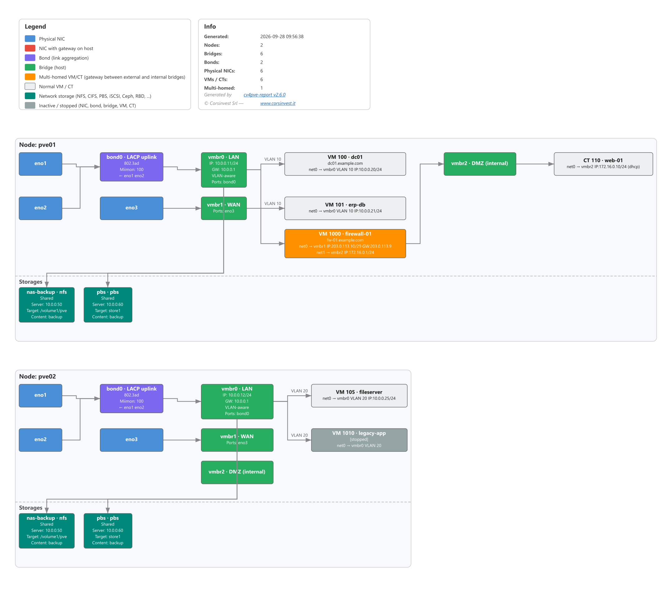
Example with two nodes, made with the same code as the report. Click to enlarge.
Layout
Section titled “Layout”For each node, one row of columns:
NICs  →  bonds  →  bridges with an uplink  →  VMs and CTs  →  internal bridges  →  VMs and CTs behind them
- - - - - - - - - - - - - - - - - - - - - - - - - - - - - - - - - - - - - - - - - - - - - - - - -Network storages, each linked to the bridge that reaches its server- Columns grow to fit their widest box; boxes grow to fit their lines.
- The order is stable from one report to the next: nodes, bridges, NICs and storages by name (
vmbr2beforevmbr10), guests by ID as a number (105before1000), gateway VMs first under each bridge. The order then changes only where that removes crossing arrows. - Arrows go left to right, from the hardware towards the guests. A guest with NICs on several bridges gets an arrow from each. The label on an arrow is the VLAN tag of the NIC, or its trunks.
- SDN VNets appear as bridges on the nodes of their zone, so guests attached to a VNet are linked too.
Colours
Section titled “Colours”| Colour | Meaning |
|---|---|
Blue #4A90D9 |
Physical NIC |
Red #E74C3C |
Physical NIC with a gateway configured on the host |
Purple #7B68EE |
Bond |
Green #27AE60 |
Bridge — Linux bridge or Open vSwitch bridge |
Orange #FF9100 |
Multi-homed VM or container: NICs on a bridge with an uplink and on an internal bridge — a candidate gateway |
Light grey #ECF0F1 |
VM or container |
Teal #00897B |
Network storage |
Grey #95A5A6 |
Inactive: NIC, bond or bridge down, guest not running, storage disabled |
What each box shows
Section titled “What each box shows”The title is the name followed by its comment, when there is one: vmbr0 · LAN, bond0 · LACP uplink.
A guest shows its type, ID and name (VM 1000 · firewall-01), a storage its name and type
(nas-backup · nfs). Then, depending on the type:
- NIC —
DOWNwhen inactive, the type when not Ethernet, address and gateway when the NIC has an IP on the host, MTU. - Bond —
DOWN, mode (e.g.802.3ad), hash policy, miimon,← slaves, MTU. - Bridge —
DOWN, type when Open vSwitch, IPv4/IPv6 address and gateway, MTU, VLANs,VLAN-aware, ports, Open vSwitch bonds and ports,IntPortwith the address of Open vSwitch internal ports (often the host management IP). - VM / CT — the status when not running (
[stopped]), the hostname when it differs from the name, then one line per NIC innet0,net1, … order:net0 (ens18) → vmbr0 VLAN 10 trunks 1-4094 IP:10.0.0.20/24 GW:10.0.0.1. The name in brackets is the interface inside the guest: from the QEMU guest agent for a VM, from the configuration for a container. Loopback,veth,docker,br-,tunandcniinterfaces are left out. A running container shows the address it has now, even with DHCP (172.16.0.10/24 (dhcp)). - Storage —
[disabled],Shared,Server:,Target:(export, datastore, pool or path),Content:.
Hover a box for a tooltip with its details, status and comment; a guest’s tooltip lists all its NICs, including the ones left out of the box. Tooltips work when the SVG is open on its own: in the HTML report, click the diagram to open it.
Gateway VMs
Section titled “Gateway VMs”A VM or container is orange when it has at least one NIC on a bridge with a physical uplink and at least one on a bridge without one. That is how a firewall or router VM looks from the outside, and it works without the guest agent.
The flip side: a multi-homed guest that does not route — a backup server with a management NIC and a
storage NIC — is orange too. Only the first level is highlighted: in a chain like
WAN → fw1 → DMZ → fw2 → LAN, fw2 is not.
Network storages
Section titled “Network storages”Storages are in their own strip below each node, because they do not carry guest traffic — the node mounts
them over a subnet. Types shown: nfs, cifs, pbs, iscsi, iscsidirect, rbd, cephfs,
glusterfs, zfs, esxi. Local storages (dir, lvm, lvmthin, zfspool, btrfs, …) are left out.
Each storage gets an arrow from the bridge whose subnet contains its server — or one of the Ceph monitors
in monhost. The bridge subnet comes from its cidr, from address + netmask, or from an Open vSwitch
internal port on it.
A storage has no arrow when its server is a host name instead of an IP — there is no subnet to match — or when no bridge covers its subnet. To get the arrow, use the IP in the storage configuration.
Limits
Section titled “Limits”- The diagram is per node: a shared storage appears under every node that uses it. Cluster-wide networks — corosync, migration — are not drawn as such.
- Multi-homed guests that do not route are shown as gateways, and only the first level of a routing chain is recognised (see above).